Arduino Usb Driver Mac
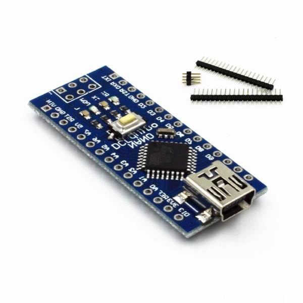
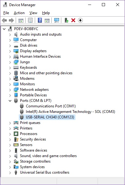
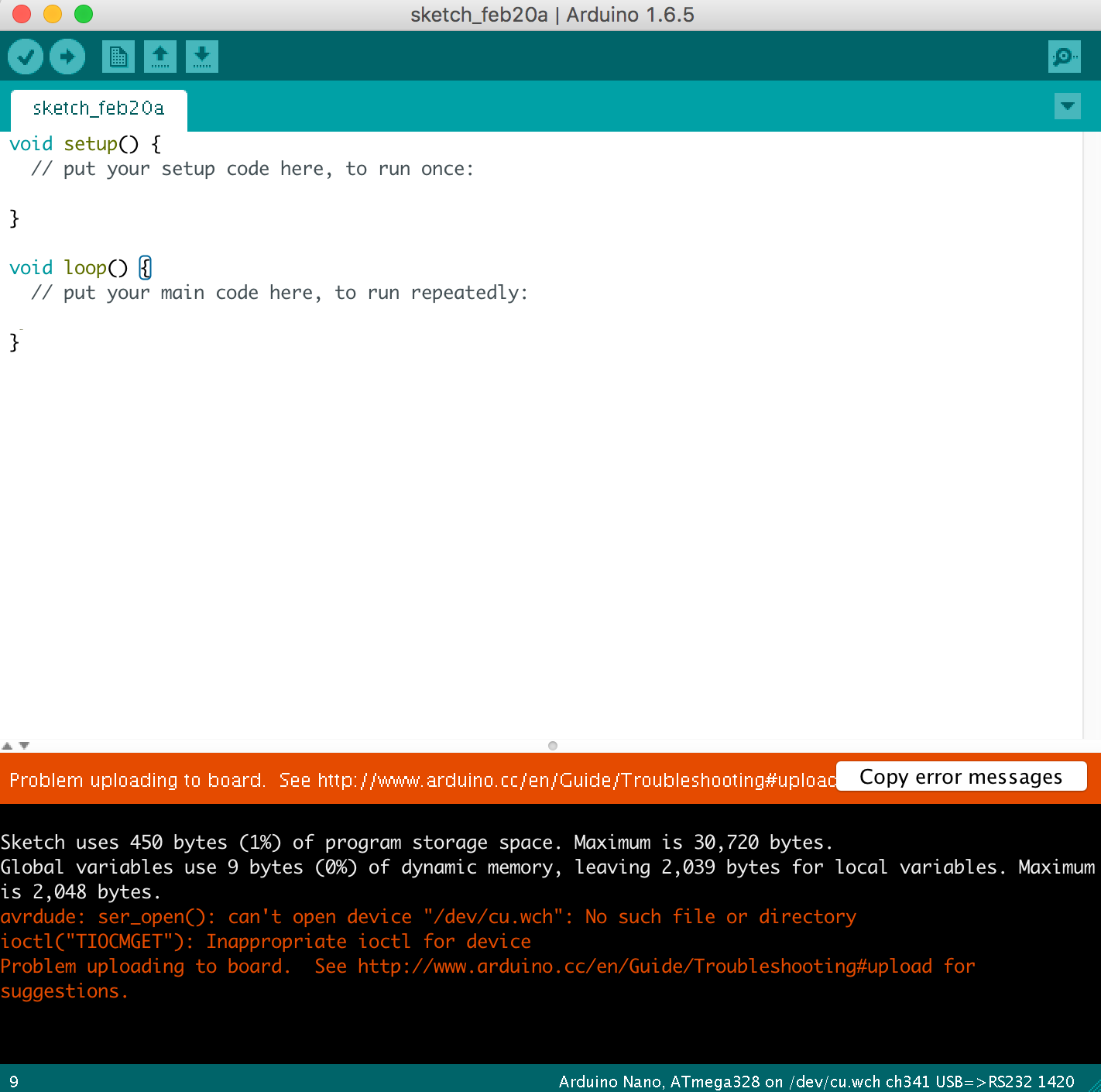
MAC OS 32/64bit (version: 1.5 – 2018/07/05) This driver is for MacOS Sierra/High Sierra. Do not install the drivers for the Mojave, because it seems that the latest versions are equipped with the built CH340/CH341 support. (MAC OS 32/64bit) for MacOS Sierra/High Sierra. Unplug any CH34. devices. Unload the old drivers if. A Windows message asks whether the driver has installed correctly. Connect your Nano. From Control Panel, open Device Manager and Ports. If installed correctly you should see an entry “USB-SERIAL CH340 (COMXX) In the Arduino IDE, go to: ToolsBoard (Select Nano) ToolsPort (Select the com port number found in Device. So I removed the FTDI drivers from my Mac so it will use Apple's drivers. Now even after doing all this when I connect my Arduino Uno to my Mac via the USB it does not get detected. I removed the kext and pkg files for the FTDI drivers and deleted them completely, still when I open the System Report I still see the FTDI USB Serial Driver entry. Install USB COM Port Driver for LinkIt ONE development board for Mac. I believe the usb/ mfa141 is the Arduino USB driver I previously installed. Once it is installed reboot your computer. If you are on the latest Mac OS you must use Arduino 1.8.12 or higher due to 64bit application enforcement that Apple put in place. Open Tools → Board:xxx and select WeMos D1 R2 & mini. Open Tools → Upload Speed and select 115200. If you're brave, you can try 230400 to upload code to the board faster, but watch the console for errors. Download a driver so your Mac recognizes the WeMos D1 board (the site looks sketchy, but I can confirm the driver is legit): Note: This.
If you are on a physical Windows 7 PC simply skip down to Step 2.
Step 1: Connect your Arduino to your Windows 7 VirtualBox machine.
Start up your Windows 7VirtualBox and plug your Arduino into your Mac. Then click on the usb icon on the lower right corer of the Virtual machine window and make sure that “FTDI FT232R USB UART [0600]” is checked as seen below:
Step 2: Download the drivers
You can download them at: http://www.ftdichip.com/Drivers/CDM/CDM%20v2.12.00%20WHQL%20Certified.zip
Step 3: Extract the zip file of the drivers into a folder on your desktop.
I’ll call the folder CDM:
| FTDI drivers extracted to a folder on the desktop called CDM |
If you are on Windows 7 you simply double click the zip file which just “opens” the zip file like it is a folder. Then click and drag the contents into another folder you must create on the desktop, I called it CDM.
Step 4: Click on the Start Menu and then right click on “Computer” and click on Properties.
| Start Menu > Right Click on “Computer” > Click on Properties |
Step 5: Open the “Device Manager.”
Click on “Device Manager” in the Computer Properties:
| Click on Device Manager |

Arduino Usb Driver Cura
Step 6: Locate the FT232R USB UART device in the device manager list:
| Device Manager: FT232R USB UART |
Step 7: Right click on “FT232R USB UART” and click on properties.
| Right-Click on “FT232R USB UART” and click on Properties |
Step 8: Click on the “Driver” tab of the Properties window and then click on the “Update Driver…” button:
| Click on the “Driver” tab and then click the “Update Driver…” button |
Step 9: Click on “Browse my computer for driver software”:
| Click on “Browse my computer for driver software” in the Update Driver Window |
Step 10: Click on “Let me pick from a list of device drivers on my computer”
| Click on “Let me pick from a list of device drivers on my computer” |
Step 11: Click on “Show All Devices” (should be automatically selected) and the click the “Next” button:
| Click on “Show All Devices” and then Click the “Next” button |
Step 12: Click the “Have Disk” Button:
Arduino Usb Driver Macos
| Click the “Have Disk” button |
Step 13: Click the “Browse” button:
| Click the “Browse” button |
Step 14: Browse to the location of the drivers.
Click on the “Desktop” Icon in the left window and browse to the folder you extracted the drivers into in step 3 and then open the folder that holds the drivers:
| Browse to the folder where you extracted the drivers in Step 3 |
Step 15: Click on the ftdibus file and click the “Open” button.
Note, the file may be called ftdibus.inf if you have the preference turned on to show known file extensions:
| Click on the ftdibus.inf file and click the Open Button |
Click on the “OK” button in the resulting window that pops up:
Arduino Usb Driver For Mac
| Click on the “OK” button |
Step 16: Select “USB Serial Convertor” from the list and click the “Next” button:
| Click on “USB Serial Converter” in the list and click the “Next” button |
Step 17: Click “Yes” to override the warning window.
It is warning you that Window cannot verify this driver (you get this error because it is a cloned Arduino board and the driver is unsigned):
| Click the “Yes” button to move on |
Step 18: Wait a while.
It will take a little while for the driver to install and then if you are successful you will get the following message, which you can click the “Close” button:
| Click “Close” to finish installing the Serial Converter |

Click the “Close” button to close the USB Serial Converter Properties window:
Step 19: Back in the Device Manager Window right-click on “USB Serial Port” and Click on “Properties”:
| In Device Manager Right-Click on “USB Serial Port” and Click on “Properties” |
Step 20: Click on the Driver tab and click the “Driver Update…” button:
| Click on the “Driver” tab and then click the “Update Driver…” button |
Step 21: Click on “Browse my computer for driver software”
| Click on “Browse my computer for driver software” again |

Step 22: Click on “Let me pick from a list of device drivers on my computer”
| Click on “Let me pick from a list of device drivers on my computer” |
Step 23: Click “Show All Devices” and click the next button:
| Click on “Show All Devices” and click the “Next” button |
Step 24: Click on the “Have Disk” button:
| Click on the “Have Disk” button |
Step 25: Click on the “Browse” button, and browse to the same folder you browsed to in Step 14:
| Click on the “Browse” button |
| Browse to the driver folder on the desktop |
Step 26: Click on “ftdiport” and click the “Open” button:
| Click on the file “ftdiport” and click the “Open” button |
Click the “OK” button to install from disk:
| Click the “OK” button to install from the disk location you chose |
Step 27: Select “USB Serial Port” from the list and click the “Next” button:
| Click on “USB Serial Port” in the list and then click the “Next” button |
Click the “Yes” button to go past the unsigned driver warning message:
| Click the “Yes” button again to go past the Unsigned Driver Warning Message |

You will get this window if you are successful and you can click the “Close” button:
| Driver successfully installed message |
You can then close the USB Serial Port Window by clicking the “Close” button:
| Close the USB Serial Port Window |
You will see this if you are successful:
| You will see the USB Serial Port listed if you are successful |
And now if you launch the Arduino software and click on Tools > Port you will see the COM port listed. Success!
| The break-out board shows up now on COM4! |
Other relevant information on this issue:
Amazon Associate Disclosure: As an Amazon Associate I earn from qualifying purchases. This means if you click on an affiliate link and purchase the item, I will receive an affiliate commission. The price of the item is the same whether it is an affiliate link or not. Regardless, I only recommend products or services I believe will add value to Share Your Repair readers. By using the affiliate links, you are helping support Share Your Repair, and I genuinely appreciate your support.
In this project, I will talk about ATtiny85, what are the tools required for Getting Started with ATtiny85 board, installing drivers for Windows OS and finally how to program ATtiny85 Microcontroller using Arduino IDE.
A Brief Note on ATtiny85
The ATtiny85 Microcontroller is possibly the smallest Microcontrollers available today. It is an 8-bit Microcontroller based on the AVR RISC Architecture. Physically, it needs only 8-pins for complete operation (although some packages like QFN16 use 16-pins just for packaging).
There are three variants of ATtiny85: ATtiny25, ATtiny45 and ATtiny85. The main difference between these three ICs is the amount of memory each device has (Flash, EEPROM and RAM).
ATtiny85 Microcontroller, the target device of this project has 8KB of In-system programmable Flash, 512B of EEPROM and 256B of SRAM.
Pin Diagram of ATtiny85
As mentioned earlier, ATtiny85 is an 8-pin Microcontroller and the most common IC package for ATtiny85 is the 8-pin SOIC. The following image shows the Pin Diagram of an 8-pin SOIC ATtiny85.
From the above pin diagram, you can observe that except for VCC and GND, rest of the 6-pins of ATtiny85 are multiplexed with multiple functionalities.
Pin Description
VCC: It is the supply voltage pin. For ATtiny85 running at a speed of 10-20MHz, the supply voltage should be in the range of 2.7V – 5.5V.
GND: Ground Pin
PORTB (PB0 – PB5): The rest of the 6-pins in ATtiny85 are Port B Pin. Port B is a 6-bit I/O Port. All the 6 port B have multiplexed operations with each pin capable of handling 3 or more operations.
RESET: It is multiplexed with PB5. It is an active LOW pin.
The following image shows the list of alternative functions on the PORTB pins.
ATtiny85 Board
Several manufacturers started developing tiny development boards with ATtiny85 as the main controller. One such board is shown in the image below.
As you can see, apart from the ATtiny85 Microcontroller IC, there are a few other components on the board like a 5V Regulator, headers for I/O pins, few passive components and a MicroUSB port for programming and power supply.
Getting Started with ATtiny85 Board
Now that we have seen a little bit about ATtiny85 Microcontroller and its development board, lets dig into the aspects of how to use this board, what are the necessary tools (like Drivers) required and also how to program the ATtiny85 Microcontroller.
Let me start with programming ATtiny85. There are couple of ways you can program your ATtiny85 but I have chosen the easiest of all: using Arduino IDE to program ATtiny85. For this, you need to make some changes to the Arduino IDE.
Next important thing is the drivers. USB Drivers for ATtiny85 Board are very important as the driver is responsible for enabling the Arduino IDE to program the ATtiny85.
Detailed Video
Before looking at the steps involved for getting started with ATtiny85 board, take a look at the following video, which basically explains the same.
Setting up Arduino IDE
The first step is to setup Arduino IDE for programming ATtiny85. Open your Arduino IDE and go to File à Preferences. In the tab that says “Additional Boards Manager URLs:”, copy and paste the following link and click on ok.
This is similar to what you might have done for ESP8266.
Now, go to Tools → Board: → Board Manager… and search for “Digistump AVR Boards”. Select the same and click on install. If the installation is successful, you can see the board in Tools → Board: option. We will come back to this later.
Installing Drivers
Next step is to install the necessary USB drivers for the ATtiny85 board. I will specify how to install drivers for Windows system. Go to the following link and download the “Digistump.Drivers.zip” file. Extract the contents of the zip file and double click on “DPinst64” application to install the drivers.
NOTE: If your system is a 32-bit system, select “DPinst” application.
Once the drivers are successfully installed, you can plug in your ATtiny85 board to the computer using an USB cable. To check if the device is detected or not, go to Device Manager on your Windows and your device will be listed under “libusb-win32 devices” as “Digispark Bootloader”.
Programming ATtiny85 with Arduino IDE
Now, you are ready to upload your first program on to your ATtiny85 Microcontroller. You don’t have to plug in your device to the computer until the IDE says so. Even if you plug in, you have to disconnect and reconnect when asked.
First step in programming ATtiny85 is to select the board in Arduino IDE. Go to Tools → Board: and select “Digispark (Default -16.5mhz)” board.
There is a user LED connected to PB1 of ATtiny85. In order to blink that LED, use the following code.
Click on upload button in Arduino IDE. Assuming you haven’t connected the ATtiny85 to the computer, the Arduino IDE will display a message saying “Plug in device now”. Connect your ATtiny85 board to the computer now and it will be programmed and the LED will start blinking.